
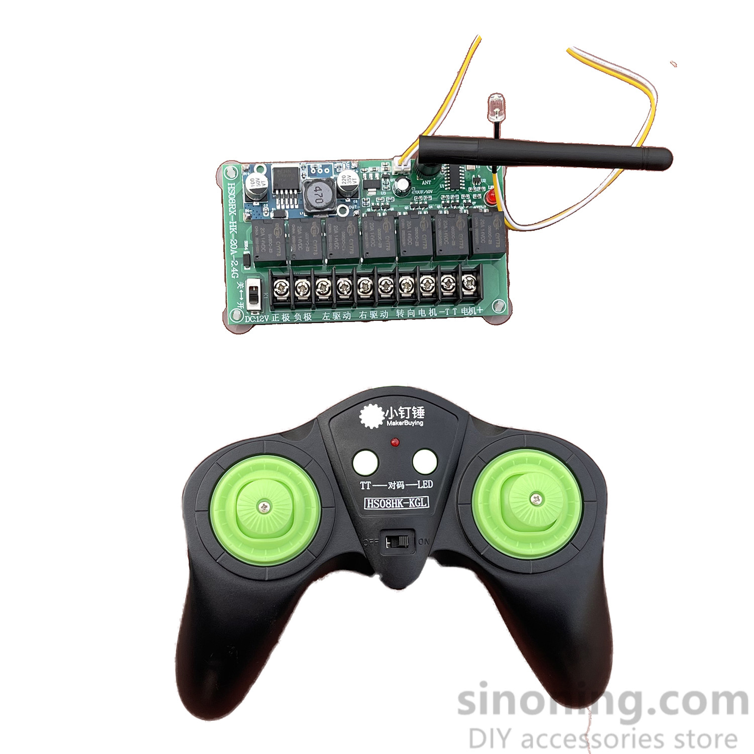
20A fighting robot car model boat model four-wheel drive car modification accessories DIY wireless remote control module XDC72
$ 13.41
Note: Enquire for additional quantities
Description interfere with each other, ensuring stable signals without mutual interference. It is suitable for retrofitting fighting robots, tank track vehicles, four-wheel drive model cars, boats, and more. [Product Parameters] 1. Remote control operating voltage: DC 2.8V~3.3V 2. Operating voltage of the receiving board: DC 7.4V~15V 3. Load power of the receiving board: four-channel output for left drive, right drive, steering motor, and TT motor, with a maximum load current of 20A per single channel, It is recommended that the continuous load current not exceed 10A. 4. Standby power consumption of the transmitter board: 15ma 5. Standby power consumption of the receiving board: 25ma 6. Remote control frequency: 2.4GHZ 7. Remote control distance: approximately 100 meters measured on a spacious open ground 8. Weight: Remote control (excluding batteries) is 121.8 grams, and the receiver board is 98.7 grams. [Frequency (Code) Alignment Method] 1. Press and hold the TT key and the LED key (code matching key) in the middle of the remote control simultaneously, then turn on the switch to power up. At this point, if the red indicator light on the remote control flashes rapidly, it indicates that the code matching mode has been entered. Within 10 seconds, turn on the switch of the receiving board to power up. Pay attention to see if the indicator light on the remote control flashes slowly a few times and then goes out, and at the same time, if the red indicator light on the receiving board flashes slowly a few times and then turns solid, it indicates that the code matching is successful. After successful pairing, there is no need to pair again when using it again. If the receiver board is damaged, a single replacement receiver board can be paired and matched with the original remote control, allowing one remote control to be paired with multiple receiver boards. 3. Tip: The remote control can operate multiple receiving boards simultaneously. To enable this feature, power on multiple receiving boards within 10 seconds after the remote control enters the pairing mode, and they will be matched with the remote control simultaneously, achieving one-to-multiple remote control. [Operating Instructions for Remote Control Receiver Board] 1. The left push rod can be controlled in the up-down, left-right directions. It can mix-control the left and right drive motors to rotate simultaneously in both forward and reverse directions, as well as one in forward and one in reverse, or one in reverse and one in forward, achieving functions such as moving forward, moving backward, and turning left or right in place; 2. The right push rod can be controlled in the up-down direction, controlling the forward and reverse rotation of an independent motor to achieve functions such as weapon movement or lifting and steering. 3. The two buttons ‘TT’ and ‘LED’ in the middle of the remote control have a self-locking flip mode (press once to start, press again to stop) to control 2-way switches, which can control the start and stop of LED lights and unidirectional motors; [Wiring and Debugging Instructions] Connect the drive motor wires to the left and right drive output pressure terminals on the receiver board according to their respective positions. Press the forward button and observe the direction of rotation of the two motors. If they both move forward simultaneously, it is normal. If one motor moves forward while the other moves backward, simply swap the two wires connected to the backward motor. Then, press the left turn button and observe the direction of rotation of the left motor. If it rotates backward and the right motor rotates forward, it is normal. If they rotate in the opposite direction, simply swap the motor wires for the left and right drives on the receiver board. [Safety tips for preventing overvoltage and overload] 1. Operating voltage range of the receiving board: DC 7.4V~15V 2. Four-channel output for left drive, right drive, steering motor, and TT motor, with a maximum load current of 20A per single channel output and a continuous load current to be established The discussion should not exceed 10 minutes. When selecting a motor, one should not solely rely on the no-load or rated current. It is essential to understand the detailed parameters of the motor’s maximum load current or locked-rotor current, It can only be used when the maximum load current or locked-rotor current is within 20A; overvoltage and overload use are strictly prohibited. Do not pretend to understand when you don’t For use only. Improper use may result in damage to the receiving board or burn out the motor; 4. It is strictly prohibited to use high-power motors and high-speed motors! If the connected motor or servo motor exhibits symptoms such as the drive chip on the receiver board becoming hot, unable to drive the motor, or the motor rotating very slowly after being turned on, it should not be used further as it may easily cause the board to burn out 5. Special precautions: 1. The positive and negative poles of the remote control and the receiver board must not be connected reversely, as reversing the connection will burn the board! 2. All electronic components of the receiver board are exposed, especially the component pins on the bottom surface. During installation, safety precautions such as insulation, waterproofing, and corrosion prevention should be taken to avoid the risk of short circuit and burnout caused by improper use! Related SKU: SNRM18 Category: DIY Toy Remote Control
Related products
-
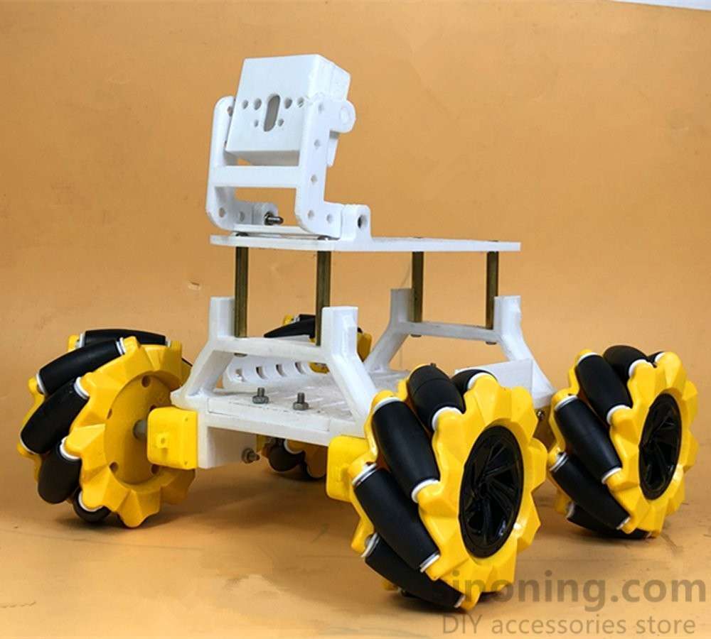 TT motor omni wheel omni smart car robot chassis 3D printing Mecanum for arduino SNC387Select options
-
20A fighting robot car model boat model four-wheel drive car modification accessories DIY wireless remote control module XDC72Select options
-
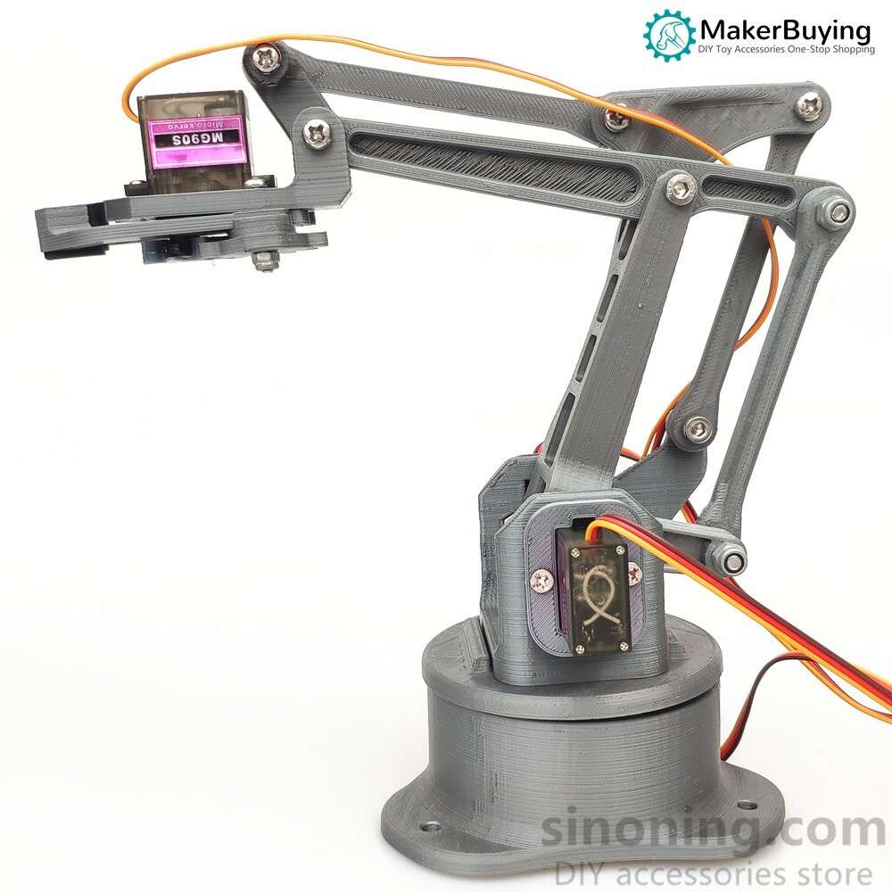 3D printing EZ silver four-degree-of-freedom robotic arm DIY robot assembly 3D printing products mg90s SNAM7900Read more
-
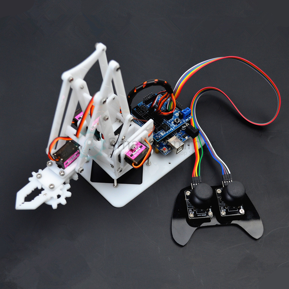 4DOF manipulator arduino Robotic arm ps2 remote control mg90s servoSelect options